Structural Analysis Concepts for Beginner Mechanical Engineers – Part 2
This series of posts introduces concepts that are missing from undergraduate (Mechanical Engineering) curricula but are essential to the safe design of industrial equipment and supporting structures. The first part in the series concerned the beam failure mode of Lateral Torsional Buckling. The second part covers a narrow but critical topic: bolted flange design due to prying forces.
Like the previous post, this is just an introduction to the concept. This article is not sufficiently in depth to provide competence in tension connection design.
Most machine design courses and textbooks cover bolted connections. They cover bolt group shear connections, some cover bolt groups in tension, but very few address checking the flanges that the bolts are trying to hold together. When a bolt group connection is resisting a load in tension, most machine design textbooks (e.g. Shigley) treat the plates as perfectly rigid. Therefore, the tension is transferred perfectly to the bolts. While this is a fine teaching method, perfect rigidity of the flanges cannot always be assumed.
Ductility is one of steel’s most advantageous characteristics. In fact, in most cases, a design that eliminated all deflection would seem overly conservative and wasteful. However, this ductility can cause unintended consequences, one of which can be found in bolted tension connections. In this type of connection an additional load is applied to a bolt from the prying action of a deflected flange. This prying can occur in any tension connection where the applied load is not coincident with the axis of the bolt. Bolt groups in tension see this type of loading in nearly all applications and therefore are subject to prying forces.
In the 15th edition of the AISC SCM the prying equations start at Part 9 Page 10. The manual states “Prying action is a phenomenon (in bolted construction only, and only in connections with tensile bolt forces) whereby the deformation of a connecting element under a tensile force increases the tensile in the bolt above that due to the direct tensile force alone”.
In this article, bolted elements are referred to as the “steel” and could be wide flange beams, channels, angles, or weldments of steel plate. If the basic configuration shown in Figure 1 and 2 are maintained, the concepts apply.
As shown in Figure 1, if the load on the web/leg is large enough to cause deflection in the flange, this can act as a lever arm about point “A” and cause a prying force under the bolt head. This prying action increases the force on the bolt above what is calculated by statics. This additional load must be calculated and accounted for or eliminated.

Figure 1
There are two ways of looking at this problem and how it can affect the bolt. First is to make the flange strong (thick) enough to avoid the prying action altogether. Secondly, we can leave the flange as designed and calculate this additional force so that it can be applied to the bolt and checked against the allowable load of the bolt.

Figure 2
For some projects, the deflection associated with prying might be acceptable. For fired heaters, air exchangers, fans, duct work and the other equipment we design/connect to in the refining industry, it is common to design the flange for no prying action. Designing for the no prying condition ensures that no flue gas or combustion air leakage at the bolted joint occurs. While deflection at these bolted connections would not impact the structural safety of the equipment, eliminating tramp air into the combustion system is always a priority in process equipment. With that in mind this article will focus on the “no prying” procedure as laid out in the AISC SCM. The ASD equations will be presented, but the concepts are the same for LRFD.
From the SCM, Equation 9-17b is arranged to give the required flange thickness in order to reduce the prying force to “essentially zero.”


Let’s break down this equation. The easiest way is to start with a tension force (T) applied through the center of the leg, this force creates a bending moment about point “A” (Figure 1). The maximum moment the flange could resist would normally be determined by the plastic moment of inertia multiplied by the yield strength, and then either Ø or Ω applied, M = Z*Fy/Ω. As stated on page 9-10 the material’s tensile strength is used in this equation because it aligns better with the experimental data collected.
The plastic moment of inertia for a rectangle around the center of gravity is:

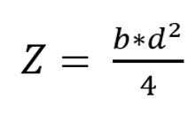
Putting this together we get:


Solving for “d” or thickness, we get equation 9-17 from the AISC SCM.
Satisfying this equation gives a flange thickness that will resist any significant deflection that could cause the prying effect.
A note on the variable “p”, as noted on page 9-12. It can be taken as 3.5*b, but should not exceed the bolt spacing. This guidance was not in the previous editions of the SCM and may be new to those using older editions. Also new in the 15th edition is the form of equation 9-17. Previously the “4” and Ω were combined to read 6.66. The new version, which is numerically the same, is much clearer.
The technique above is commonly used for sizing steel members, but there is another way to look at equations in the SCM procedure.
Consider a hypothetical situation where you have a beam that is already sized and built, and the customer wants to hang piping from it (because they always want to hang piping from it). The piping support connection is often a pipe hanger hanging from the beam flange or something similar. The additional loads on the member are typically small enough to not require any changes to the beam size, the end connections, or the overall structure layout but should be checked. The local stresses on the beam also need to be considered. The flange prying procedure can be used to see how many bolt pairs would be required to hold the load with the existing flange size. The load would be divided by the allowable force on the flange at each bolt. This number is rounded up to the nearest even number. This is how many bolts the existing flange requires to support the intended load. This number of bolts must also be large enough for the bolt themselves to support the load.
If the “no prying” configuration is not required, the loading on the bolt with the effects of prying action can be determined by equation 9-27. If the available strength of the bolt is not sufficient to carry the load, more bolts must be added. Adding more bolts will reduce the tension per bolt and reduce the prying force experienced by the bolt.
I hope this introduction to the concept of prying at bolted connections helps you design connections that are safer and more efficient.
A few notes:
- Gussets between bolt holes can be used to stiffen the flange. This is not covered here or in the Manual. A source of information that might help is “A Yield Line Component Method for Bolted Flange Connections” by Bo Doswell.
- CICIND has alternative equations that might be helpful.
- While this is not apparent from Figure 9-4, the distance b’ (from the center of the angle leg to the edge of the bolt hole) as the moment arm on an angle is based on the assumption that the actual connection is a back to back angle. If the connection is a single angle (like on ductwork flange connection) it is suggested that the b’ dimension be at least to the outside of the angle. Suggested reading is Modern Steel Construction “Steel Interchange” February 2015.
- A couple of additional suggested articles: “A Quick Look at Prying” and “A Slightly Longer Look at Prying”, both by Caro Lini. Of course, chapter 9 of the SCM should be read as well.
References
American Institute of Steel Construction. (2017). Steel Construction Manual . Chicago: American Institute of Steel Construction.