Structural Analysis Concepts for Beginner Mechanical Engineers – Part 1
Admittedly, this blog post will be geared toward a small audience. It’s for a recent (or maybe not so recent) graduate with a Mechanical Engineering degree who is designing the structural support of some piece of equipment. If this is you, you were probably given a few drawings and a shiny new copy of (insert favorite structural program here) and then told “You’re an engineer; you can figure it out. Besides the program does most of the work.” This is a common occurrence in the petrochemical industry. Structural analysis programs are robust and incredibly helpful, but if you do not understand the program’s expected inputs and what it actually checks, it is very easy to inaccurately model your structure.
A concept that must be understood yet is not usually covered in mechanical engineering courses is Lateral Torsional Buckling (LTB) of beams in flexure.
Both Prandtl and Michell separately published analysis of lateral stability in 1899. The phenomenon of beams that often do not reach the capacity predicted by yielding equations has been known for over a century. Basic observations of the final deformations of many failed beams do not show the type of deformation expected by plastic failure, but rather a beam twisted transverse to the original load (Brzoska, 1991).
This is a very basic overview of the concept. For a detailed explanation of LTB there is an exhaustive supply of articles to be found. AISC also has videos covering a wide variety of topics, including LTB. While understanding what is happening at the grain size level is not required, I believe that knowing the basics of the failure mode will help to understand possible corrective methods.
Simply supported beams while under vertical loading will deflect causing one flange to be in compression and one flange to be in tension. In most (but not all) cases, the compression flange will be on top. The compression flange can be viewed similar to a column. Once the compression flange reaches its buckling capacity, it will try to displace at the midpoint between the torsionally restrained end points. The tension flange will not allow the compression flange to buckle downward, so it must move laterally to relieve the stress. The tension flange also limits the lateral movement of the beam cross section as a whole, causing the compression flange to move to the side farther than the tension flange. This mismatch in lateral displacement causes a twisting motion (torsion) in the beam (see Figure 1). For this twisting motion, the center of rotation is below the bottom flange and the cross section rotates as an undeformed shape.
Returning to the analogy of the compression flange being like a column, there are two ways to resist LTB: selecting a bigger beam (with a greater resistance to torsion), or, like a column, reduce the unbraced length. The length between unbraced points is often the most effective variable to consider when trying to counteract LTB and bring the beam’s capacity closer to its plastic moment (Mp).

Figure 1
However, simply bracing the beam in the lateral direction is insufficient to consider the beam braced for LTB. Specifically, the compression flange must be braced from lateral movement which, in turn, prevents torsion. The distance between points of lateral and torsional bracing for the compression flange is called the unbraced length and is represented by Lb in the Steel Construction Manual (SCM). For example, Figure 2 (below) is not braced. While the beam is constrained in lateral movement, the compression flange can rotate.

Figure 2
Figure 3 (below) is a laterally braced beam whose rotation is restricted; therefore, it does have a properly braced point.

Figure 3
With the influence of LTB being based on the unbraced length, AISC identified three categories of unbraced lengths for each beam. Each of these lengths has a different type of LTB failure. As illustrated in Figure 4, the three ranges of unbraced length are plastic, inelastic LTB, and elastic LTB. The ranges are set by following lengths, 0’-0” to Lp (plastic length), from Lp to Lr (inelastic length), and Lr to infinity (theoretically). The length for Lp and Lr are listed for each beam in AISC SCM Table 6-2 and the equations can be found in AISC SCM, (F2-5 and F2-6).
Per AISC SCM table F1.1, the bending moment capacity of a compact beam is based on two modes of failure— yielding and LTB. Pure yielding failure, as predicted by the plastic moment calculations (Eq. F2-1), can be reached when the beam has an unbraced length less than Lp. Many structural elements have an unbraced length of zero. For example, modern fired heaters have beams spanning the cross section supporting the floor from underneath. These beams are continually braced at the compression flange by the welded floor plate; therefore, full plastic moment can be achieved.
If the beam’s unbraced length falls between Lp and Lr the beam will fail by inelastic LTB. The torsional and lateral deformation will be permanently set. The moment required for this failure can be found at AISC SCM Eq. F2-2.
The third mode of LTB has an unbraced length long enough that the beam fails to LTB, but the deformation is not permanently set. The equation for this moment limit is F2-3.
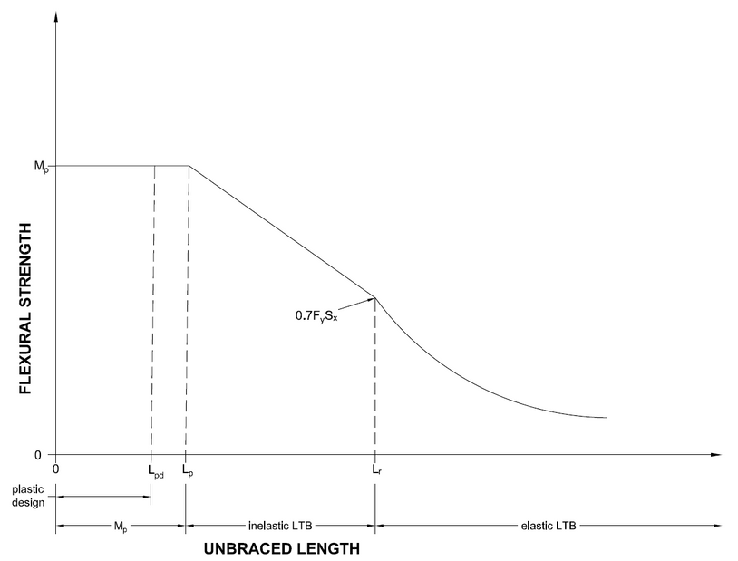
Figure 4
At this point, you may be thinking to yourself, “I don’t have to worry about calculating these lengths and determining reduced capacities because I use (insert program name here).” You are most likely correct. Most structural analysis programs will determine the capacity of a beam based on its unbraced length as it is modeled. This puts the responsibility on you to make sure the model accurately represents how the piece of equipment will be manufactured.
You must remember that just because a beam may be braced for lateral movement, if the brace does not engage the compression flange, the beam must be considered unbraced. Understanding the requirements to consider a point braced will influence how your model is arranged.
The two examples below show the difference between how steel arrangements must be modeled in RISA 3d. Figure 5 is the accurate way to model the beam/brace configuration, similar to Figure 2. Note that the beam from node 1 to 2 is shown as one continuous beam. The unbraced length used in the LTB calculation is the entire length of the beam.

Figure 5
Figure 6 (below) shows one of the correct ways to model the beam/brace configuration from Figure 3. Because the brace restricts the lateral movement of the compression flange and therefore restricts rotation, the length between end point and the brace point is the appropriate unbraced length. This shortening of the unbraced length will increase the allowable moment on the beam.
If the engineer is unaware of requirements associated with braced points for LTB, it might seem reasonable to model a beam/brace configuration like Figure 2 with the beam divided in two pieces (similar to Figure 6). After all, there is a brace intersecting the beam at that point. However, modeling the assembly this way would greatly overestimate the moment capacity of the beam.

Figure 6
A few notes:
- AISC bases the calculations for the Lp and Lr lengths on the assumption that the beams are what the guide refers to as “compact shapes for flexure.” A compact shape for flexure is a structural member that is proportioned so that neither the flange nor the web will buckle locally before the plastic moment is achieved. For wide flange beams made from 50ksi yield strength steel, there are a few shapes in the SCM that are considered non-compact. These shapes are marked in Table 1-1 in the SCM.
- The LTB capacity calculations are based on the assumption that the beam is subject to a uniform moment load along the entire length of the beam and braced at the ends. This type of loading rarely occurs in modern structures. When point loads or uniform weight loads are applied to the beam, the effects of LTB are overstated and need to be adjusted. The allowable moment in the beam is adjusted using a modifier (Cb). This modifier will be discussed in future posts, if the reader would like a more in-depth treatment at this moment, it is explained in the SCM.
- This bracing does not apply to cantilevered beams. They are a special case that will be discussed in future posts.
- At points where a continuous beam crosses over a column, the moment diagram inverts and the compression flange is on the bottom flange. In this configuration, it would seem logical that the column acts as a brace that would not allow the compression flange to move laterally. This is not true for reasons that are beyond the scope of this post. Just know that points of inflection are not considered braced points.
I hope this basic explanation of Lateral Torsional Buckling helps you to more accurately model your structures. More importantly, if this is your introduction to the concept, I hope this article has made you aware that there are always new concepts that require your continued learning and gives you a place to start that journey.